- 您现在的位置:买卖IC网 > Sheet目录2000 > IDT82V3285AEQG (IDT, Integrated Device Technology Inc)IC PLL WAN SE STRATUM 100TQFP
IDT82V3285A
WAN PLL
Programming Information
127
August 7, 2009
7.2.10
SYNCHRONIZATION CONFIGURATION REGISTERS
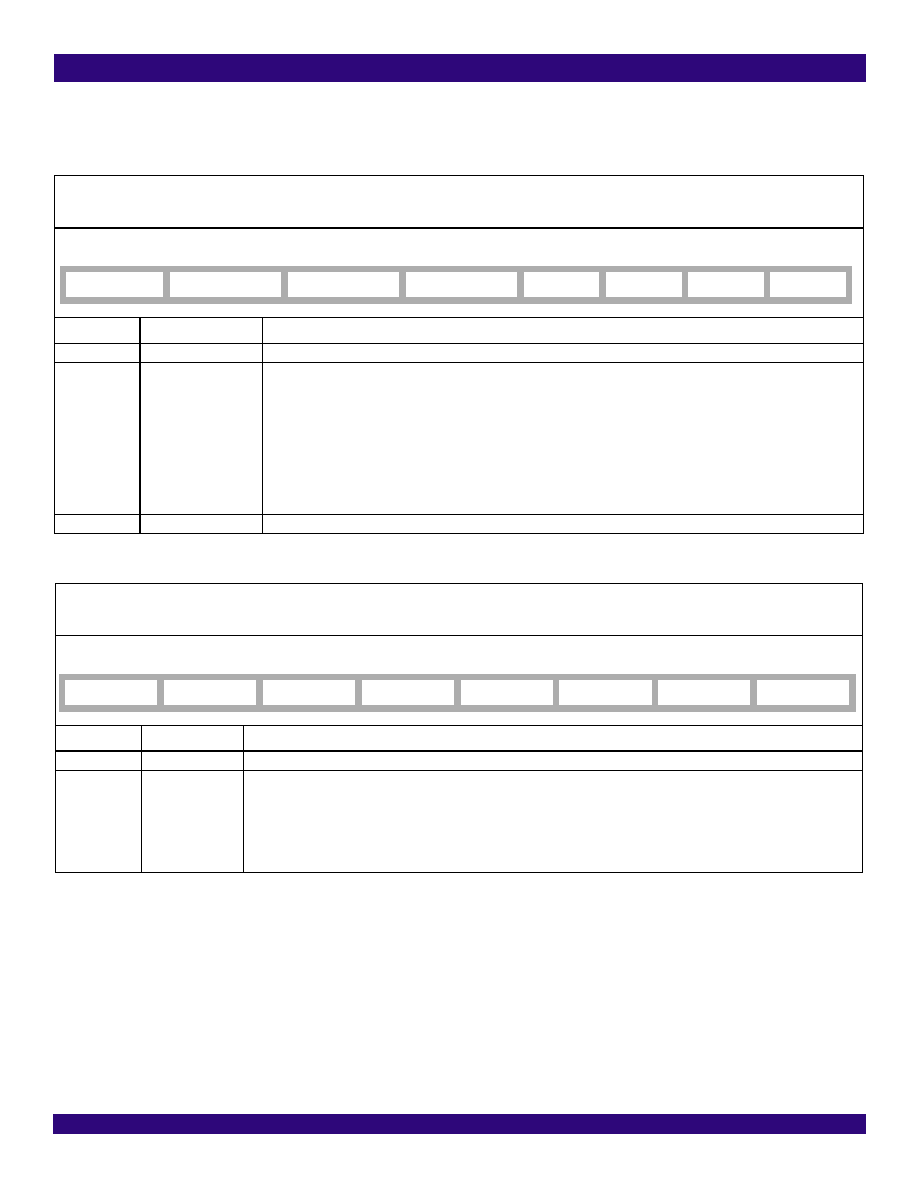
SYNC_MONITOR_CNFG - Sync Monitor Configuration
SYNC_PHASE_CNFG - Sync Phase Configuration
Address:7CH
Type: Read / Write
Default Value: X0101011
Bit
Name
Description
7
-
Reserved.
6 - 4
SYNC_MON_LIMT[2:0]
These bits set the limit for the external sync alarm.
000: ±1 UI.
001: ±2 UI.
010: ±3 UI. (default)
011: ±4 UI.
100: ±5 UI.
101: ±6 UI.
110: ±7 UI.
111: ±8 UI.
3 - 0
-
These bits must be set to ‘1011’.
Address:7DH
Type: Read / Write
Default Value: XXXXXX00
Bit
Name
Description
7 - 2
-
Reserved.
1 - 0
SYNC_PH1[1:0]
These bits set the sampling of EX_SYNC1 when EX_SYNC1 is enabled to synchronize the frame sync output signal. Nomi-
nally, the falling edge of EX_SYNC1 is aligned with the rising edge of the T0 selected input clock.
00: On target. (default)
01: 0.5 UI early.
10: 1 UI late.
11: 0.5 UI late.
7
6
5
4
3210
-
SYNC_MON_LIMT2
SYNC_MON_LIMT1
SYNC_MON_LIMT0
----
76543210
----
--
SYNC_PH11
SYNC_PH10
发布紧急采购,3分钟左右您将得到回复。
相关PDF资料
IDT82V3285EQG
IC PLL WAN SE STRATUM 100TQFP
IDT82V3288BCG
IC PLL WAN 3E STRATUM 2 208CABGA
IDT82V3355EDG
IC PLL WAN SYNC ETHERNET 64TQFP
IDT82V3358EDG
IC PLL WAN SYNC ETHERNET 64TQFP
IDTCSPT857DNLG8
IC PLL CLK DVR SDRAM 40-VFQFPN
IDTCV105EPVG8
IC CLK GEN DESKTOP PC 48-SSOP
IDTCV110NPVG
IC FLEXPC CLK PROGR P4 56-SSOP
IDTCV115-2PVG
IC FLEXPC CLK PROGR P4 56-TSSOP
相关代理商/技术参数
IDT82V3285AEQG8
制造商:Integrated Device Technology Inc 功能描述:IC PLL WAN SE STRATUM 100TQFP
IDT82V3285DQG
功能描述:IC PLL WAN STRATUM 100-TQFP RoHS:是 类别:集成电路 (IC) >> 时钟/计时 - 专用 系列:- 标准包装:1,500 系列:- 类型:时钟缓冲器/驱动器 PLL:是 主要目的:- 输入:- 输出:- 电路数:- 比率 - 输入:输出:- 差分 - 输入:输出:- 频率 - 最大:- 电源电压:3.3V 工作温度:0°C ~ 70°C 安装类型:表面贴装 封装/外壳:28-SSOP(0.209",5.30mm 宽) 供应商设备封装:28-SSOP 包装:带卷 (TR) 其它名称:93786AFT
IDT82V3285DQGT
功能描述:IC PLL WAN STRATUM 100-TQFP RoHS:是 类别:集成电路 (IC) >> 时钟/计时 - 专用 系列:- 标准包装:1,500 系列:- 类型:时钟缓冲器/驱动器 PLL:是 主要目的:- 输入:- 输出:- 电路数:- 比率 - 输入:输出:- 差分 - 输入:输出:- 频率 - 最大:- 电源电压:3.3V 工作温度:0°C ~ 70°C 安装类型:表面贴装 封装/外壳:28-SSOP(0.209",5.30mm 宽) 供应商设备封装:28-SSOP 包装:带卷 (TR) 其它名称:93786AFT
IDT82V3285EQG
功能描述:IC PLL WAN SE STRATUM 100TQFP RoHS:是 类别:集成电路 (IC) >> 时钟/计时 - 专用 系列:- 标准包装:1,500 系列:- 类型:时钟缓冲器/驱动器 PLL:是 主要目的:- 输入:- 输出:- 电路数:- 比率 - 输入:输出:- 差分 - 输入:输出:- 频率 - 最大:- 电源电压:3.3V 工作温度:0°C ~ 70°C 安装类型:表面贴装 封装/外壳:28-SSOP(0.209",5.30mm 宽) 供应商设备封装:28-SSOP 包装:带卷 (TR) 其它名称:93786AFT
IDT82V3285EQG8
制造商:Integrated Device Technology Inc 功能描述:IC PLL WAN SE STRATUM 100TQFP
IDT82V3288
制造商:IDT 制造商全称:Integrated Device Technology 功能描述:WAN PLL
IDT82V3288BC
制造商:IDT 制造商全称:Integrated Device Technology 功能描述:WAN PLL
IDT82V3288BCG
功能描述:IC PLL WAN 3E STRATUM 2 208CABGA RoHS:是 类别:集成电路 (IC) >> 时钟/计时 - 专用 系列:- 标准包装:1,500 系列:- 类型:时钟缓冲器/驱动器 PLL:是 主要目的:- 输入:- 输出:- 电路数:- 比率 - 输入:输出:- 差分 - 输入:输出:- 频率 - 最大:- 电源电压:3.3V 工作温度:0°C ~ 70°C 安装类型:表面贴装 封装/外壳:28-SSOP(0.209",5.30mm 宽) 供应商设备封装:28-SSOP 包装:带卷 (TR) 其它名称:93786AFT